full port 1/2” – 1”
hot forged brass ball valve
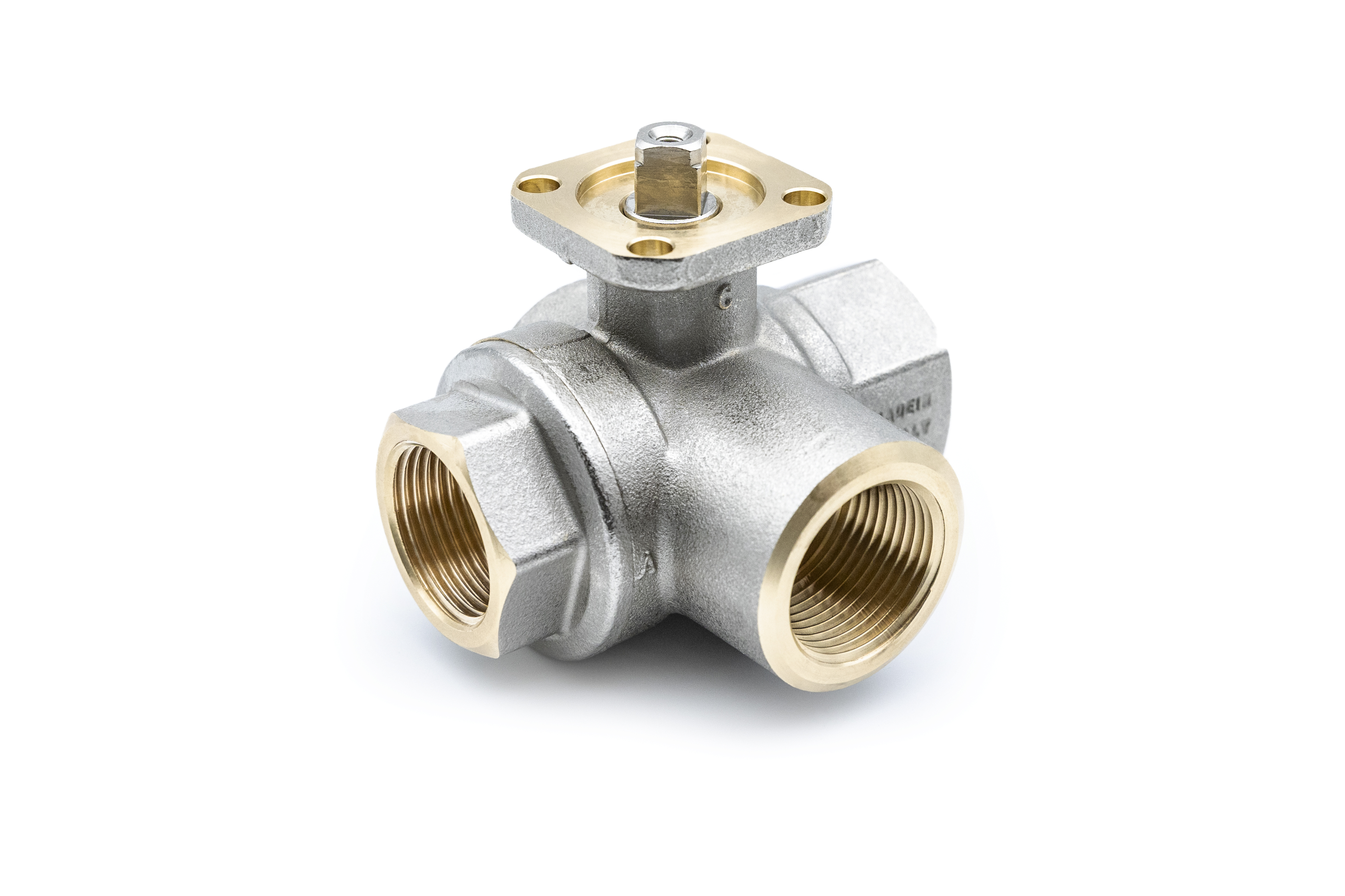
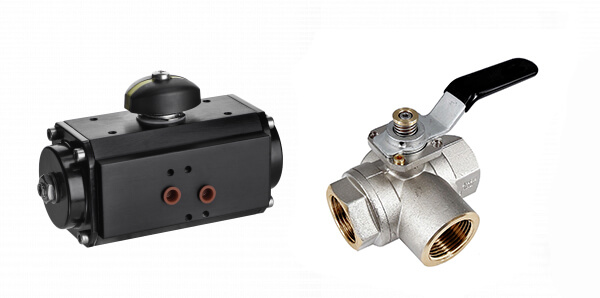
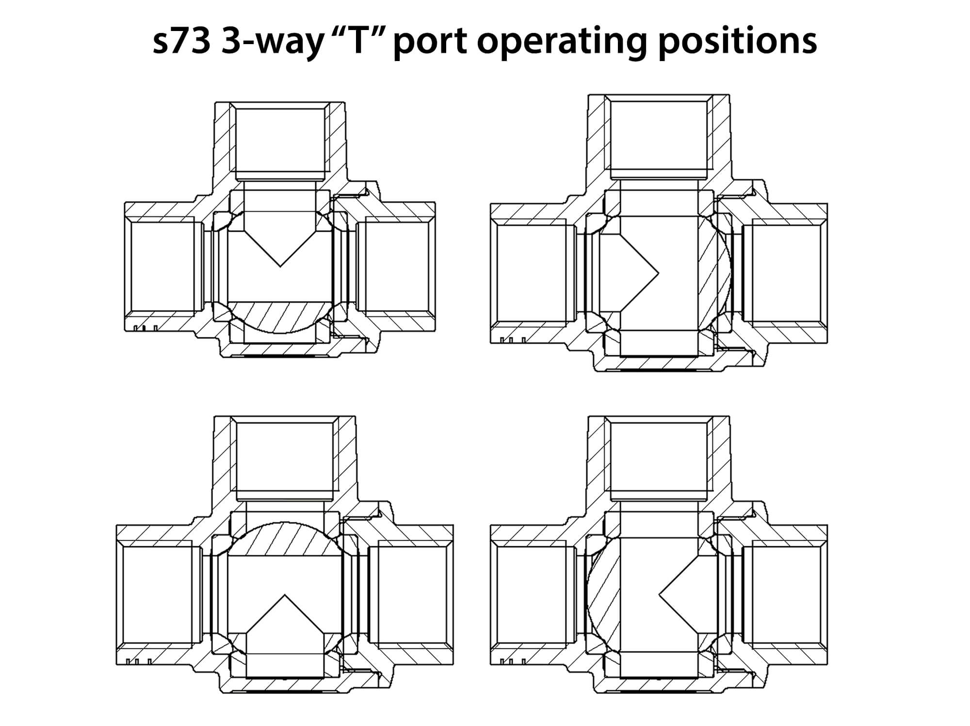
In many situations a single multi-port valve can replace several 2-way valves to reduce cost, simplify automation and conserve space. The s.7300L series have a ball seal at every port, and offer a wide variety of possible flow configurations. Positive shutoff can be achieved at any of the exiting ports. By specifying the appropriate ball port configuration, the T-port design allows flow direction to be adjusted for virtually any situation and is ideal for mixing applications. Our s73 multi-port valves can reduce the number of valves required in piping systems and can significantly lower overall costs by allowing the replacement of two or three conventional straight-line valves, eliminating excess fittings and simplifying automation.
NOTE: approvals apply to specific configurations/sizes only.
品名 | 数量 | 材料 | |
---|---|---|---|
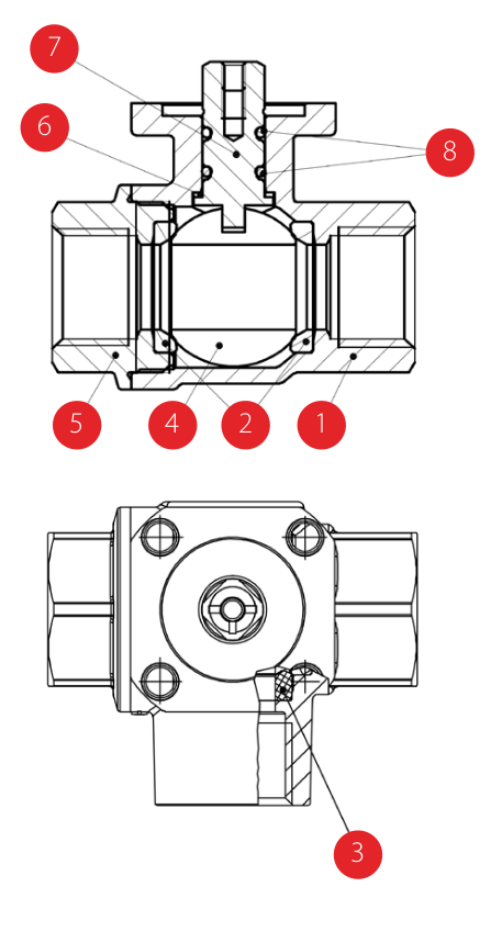
1 | Nickel plated body (external nickel plated, unplated inside) | 1 | CW617N |
2 | Seat | 2 | PTFE |
3 | Seat | 2 | PTFE |
4 | Chrome plated ball | 1 | CW617N |
5 | Nickel plated end-cap (external nickel plated, unplated inside) | 1 | CW617N |
6 | Washer | 1 | PTFE carbon filled 25% |
7 | Nickel plated stem O-ring design | 1 | CW617N |
8 | O-Ring | 2 | FPM |
9 | Screw handle stop | 1 | CW617N |
10 | Spring | 1 | 1.4310 / AISI 302 |
11 | Unplated spring bushing | 1 | CW617N |
12 | Stainless steel screw | 1 | 1.4301 / AISI 304 |
13 | Geomet® plated steel handle | 1 | DD11 (EN10111) |
14 | Black dipped coating | 1 | PVC |
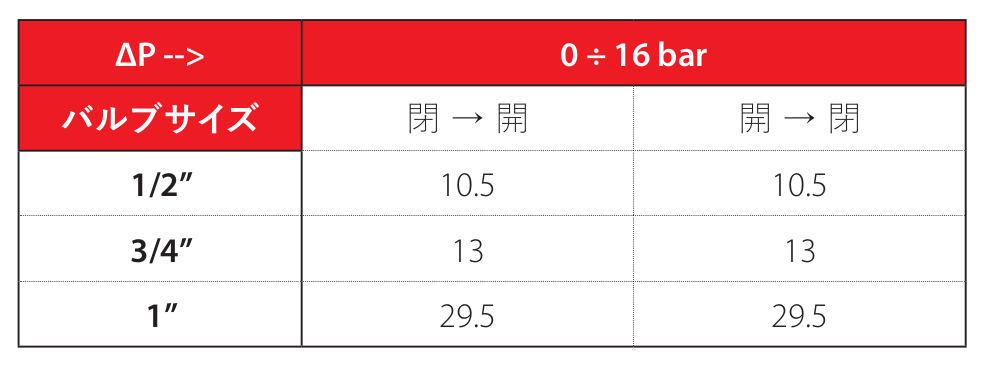
Valve torque can vary according to operating frequency, temperature and friction characteristics of the media.
If media has more or less friction than water, multiply torque by the following factors.
Lubricating oils or liquids | 0.8 |
Dry gases, natural gas, | 1.5 |
Slurries or liquids bearing abrasive particles | 1.5÷2.5 |
With the configuration of T-Ball a stop pin can be screwed in any position of the 4 provided in the flange (1, 2, 3 or 4) and the lever can be rotated freely through 90°, the flow assumes the directions indicated in the diagram; in case of need the lever can be pulled upwards and you can reach any of the four possible positions.
An alternative is to mount 2 pins in 2 near holes (e.g. 1 and 2). In this case, the valve does not assume a predetermined position but can be actuated just by pulling the lever towards the top.
The valve allows also to block the lever thanks to the addition of a lock on the lever’s protrusion (in the drawing you can see position 2).
The mixing configuration is achieved by placing the pin in position 2. The flows to be mixed enter through A and C and exit through A+C.